Finally it’s time to put the CoffeePID to work. I have testet the software and hardware outside the Gaggia Classic and am very confident, that the integration will not be that big of a deal. Let’s see how this turns out… But first a little service and security advice:
Be aware, that the machine is internally working with 230V (or 110V, depending, where you are). So working on a powered machine can be very dangerous! This is why you should ALWAYS disconnect the power cable in the back BEFORE opening the machine and start fiddling with its internals.
Placement
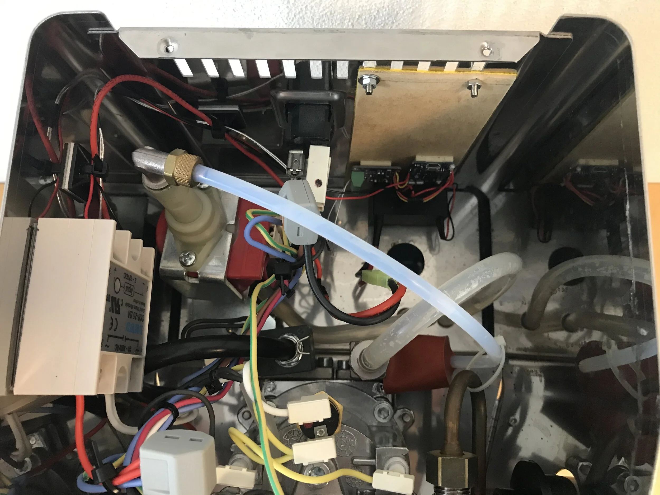
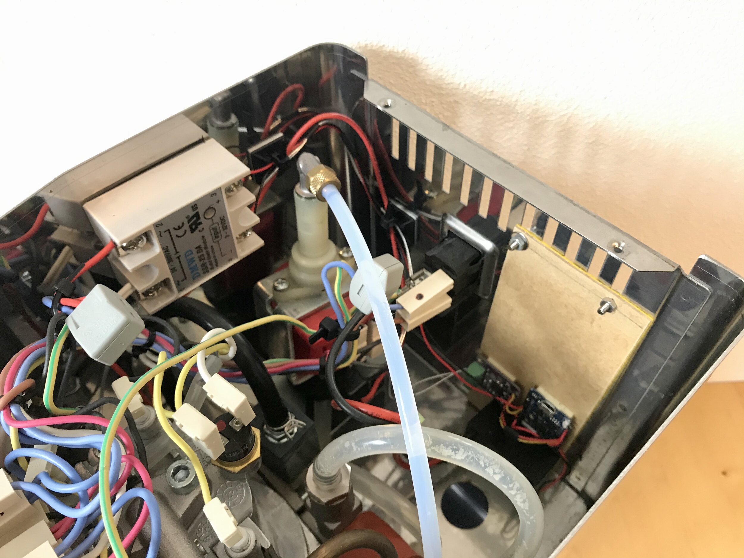
The first time I took a closer look inside the machine to plan the component placement I was a bit disappointed, as the first plan to simply screw the SSR to the slots on the backside the machine didn’t work out. Besides that setback it turned out that the placement should be quite easy. I wanted to place the power supply, the WEMOS and the MAX31865-breakout on a mounting plate and put that on the backside of the machine, right behind the water filling funnel. That funnel makes it a bit tricky and is why I placed the components as close to the bottom as possible. Keeping those parts close together is generally a good idea, so we can use shorter cables and reduce the mess a bit. The SSR will be placed to the left side of the machine, this way it is close to the position of the original thermostat, simplifying wiring. There is also a lot of space below the front panel, but putting the relay there would be too much of a hassle, if you need to access the ports. I fixed the SSR using double sided thermal adhesive tape, this way it can dissipate the heat via the machine body.
The PT1000-element
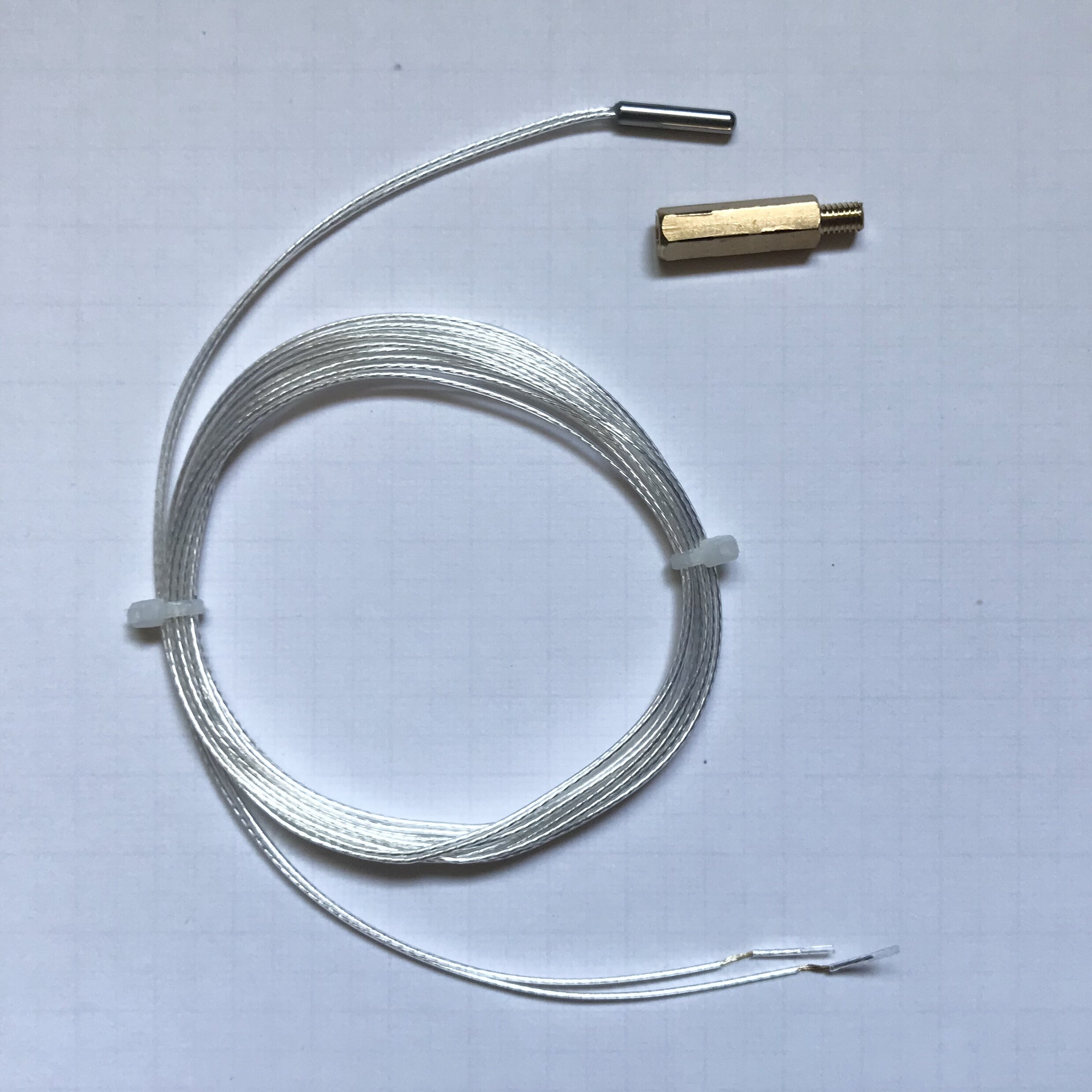
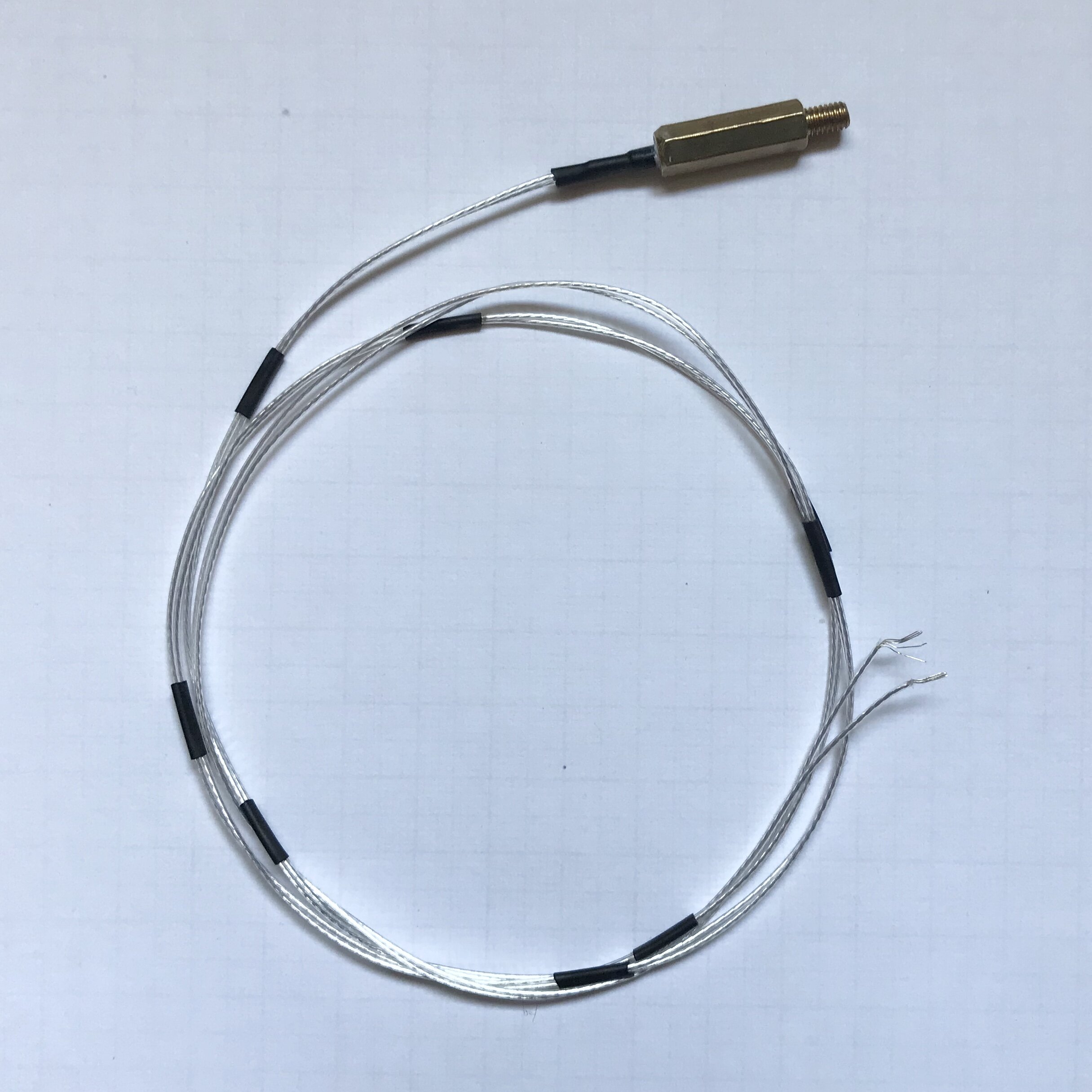
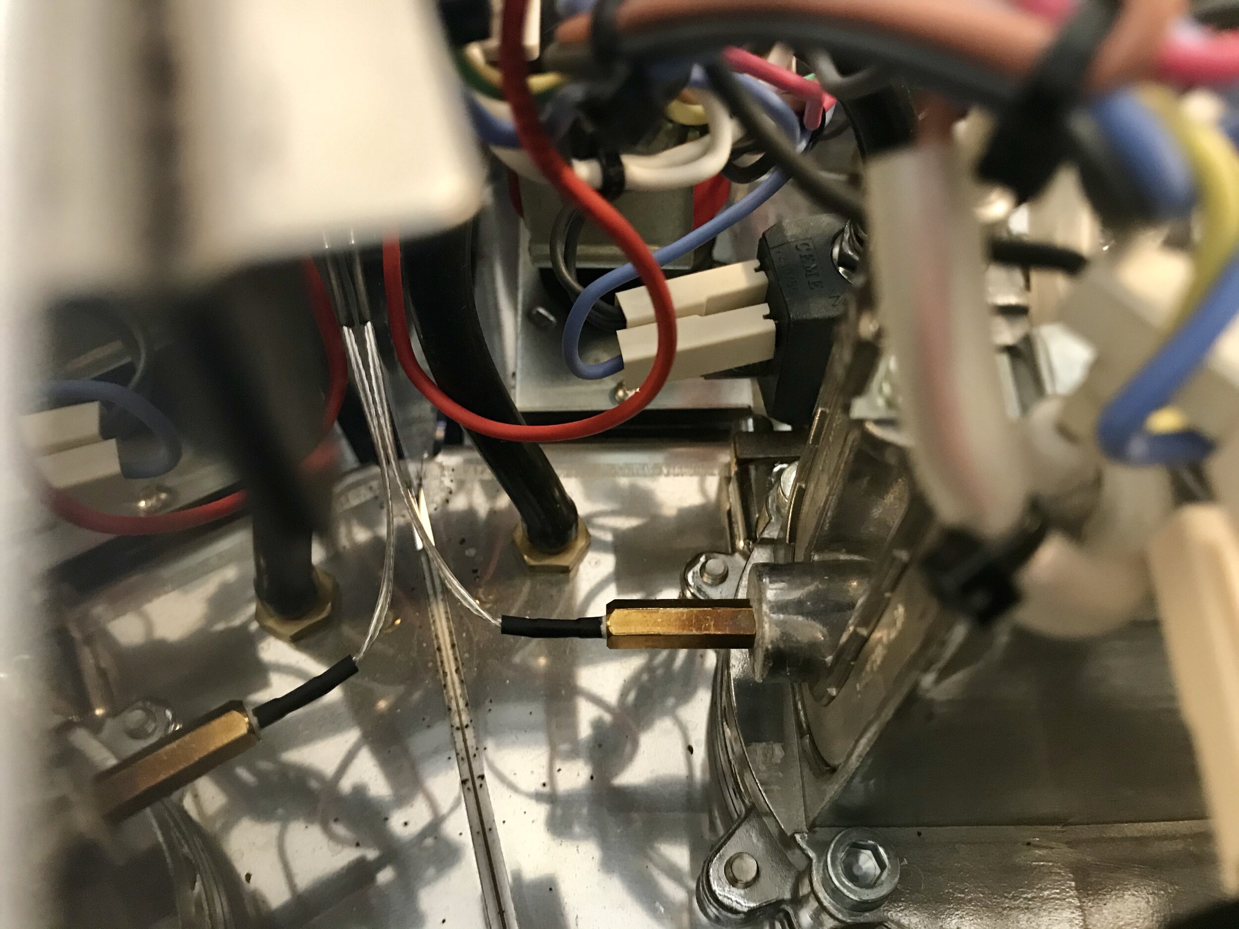
Obviously I had to find a solution to the fact, that the thermal element is a small cylindrical element and the thermostat it replaces has a male M4 screw thread. But there is a simple fix, I just glued the PT1000-element inside a M4 spacer using thermal adhesive. That way the PT1000 is just a simple drop-in replacement to the current boiler thermostat. At least that is what I thought. Unfortunately if you only remove the top plate / water funnel, it is very difficult to screw in the PT1000. I only managed this with the help of my wife and a lot of patience. For the not so patient type it is a good idea to unscrew the boiler from the machine to put the new thermoelement in place.
Wiring
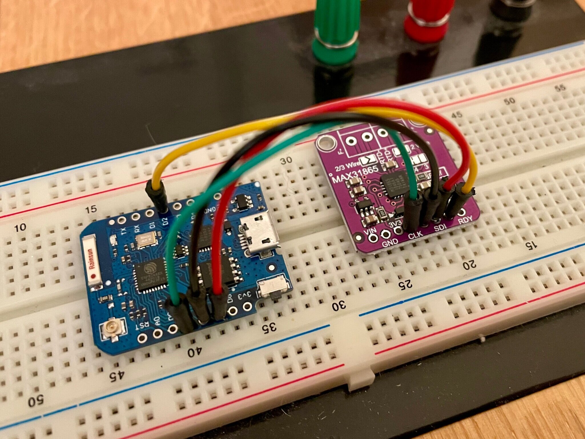
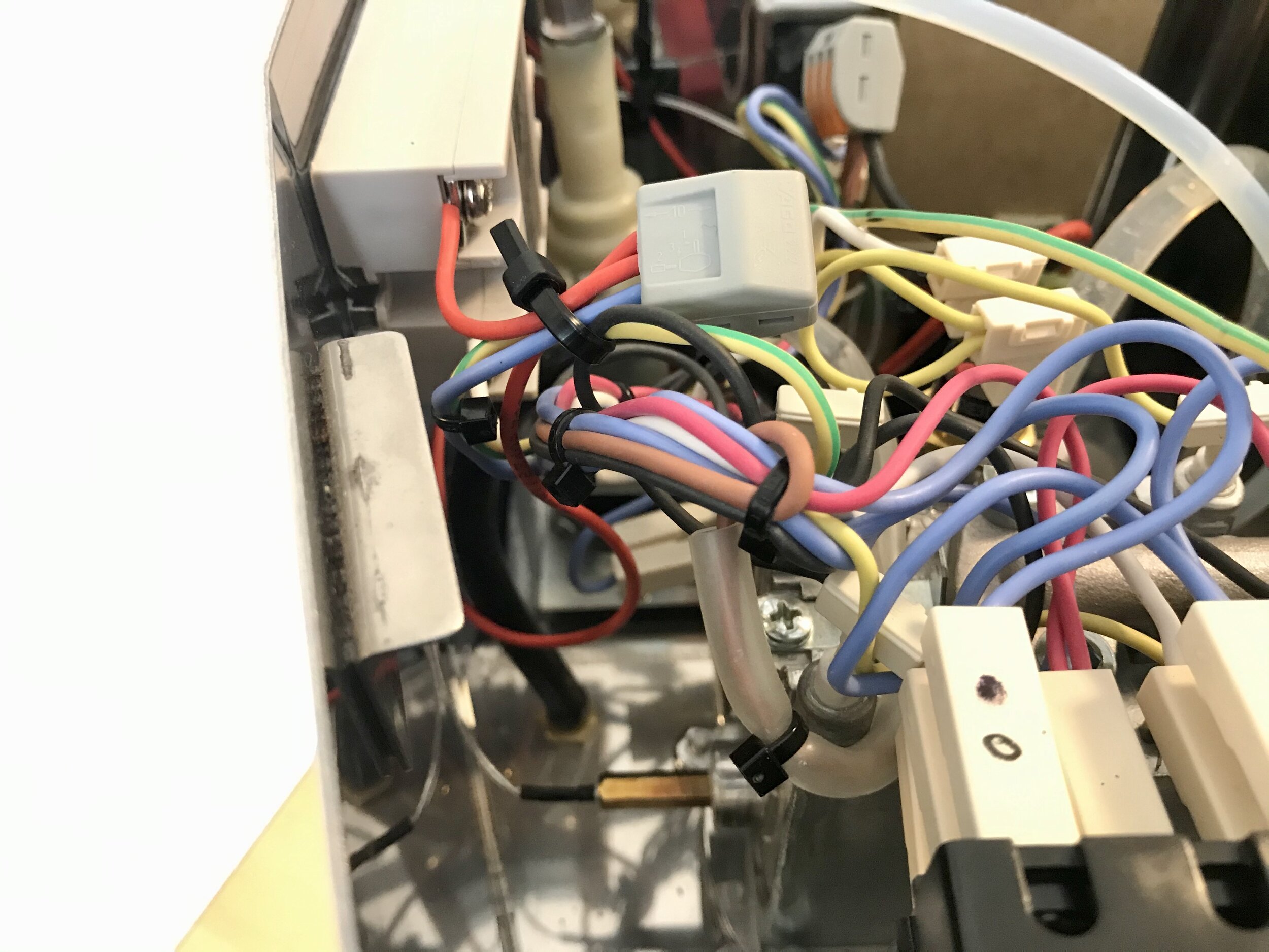
As I already had a look at wiring schematics of the machine, I was confident, that the integration should be not too hard. And as it turns out the modifications are really minimal. Starting at the thermostat, it is initially wired to the main power switch at the front and to the heater (and heating light). As this is now the job of the SSR (switching the heater), I simply connected the thermostat wires to the relay. Now there is only one thing missing: the power supply for the CoffeePID. As I want the CoffeePID to switch on with the machine, I need one wire from the just connected “input-wire” of the relay, which is switched by the main switch in the front and one wire that I can easily grab from the back.
LAST MINUTE CHANGES
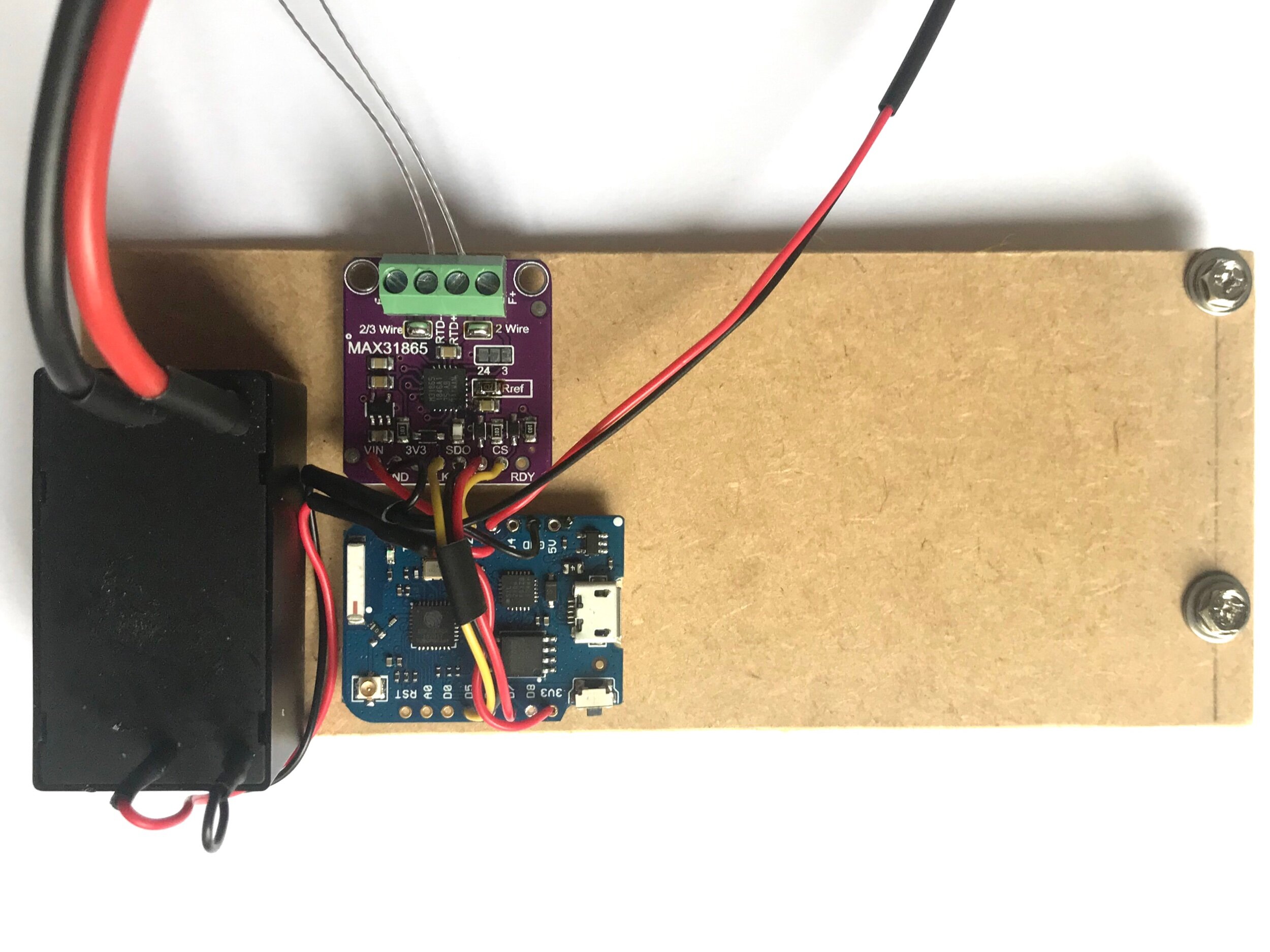
During the integration planning I realized one possible issue. I want to be able to connect to the ESP (e.g. via USB serial monitor) after the CoffeePID has been integrated, also when the coffee machine is running. But it was planned to permanently connect the power supply to the power switch, so the ESP would be powered from the power supply and via USB, if connected. It is generally not advised to run a microcontroller board this way, as the power distribution on most boards is not designed for this mode and may damage the board permanently. To prevent this I simply added a connector to the AC side of the power supply, this way I can disconnect the power when connecting to the Wemos via USB. This is how the final build looks like and how I placed it in the Gaggia Classic.

POWER ON
As noted before, the temperature regulation is currently very simple, but I wanted to see the results first before tweaking the code. So I used the serial plotter of the Arduino IDE to create a chart of the initial heat up:
Initial temperature curve of CoffeePID in my Gaggia Classic
I am actually pretty ambivalent about this first graph. But what was I expecting? On the one hand it clearly shows that the build is working as planned. Below the target temperature the ESP switches the relay and therefore the heater on. Above the target temperature the relay is switched off, letting the water cool down. Unfortunately this is a pretty inert system leading to substantial overshoot and a quite large oscillation. Regarding temperature stability this is not what I was looking for, but I already indicated, that this might not be the final implementation. And with this new task of optimizing the temperature regulation, it seems that this will not be the last post in this series.
I hope you enjoyed the journey so far and stay with me on my way to a better coffee experience.